CACT: wickless flat-plate heat pipe
The figures from the writeup, one per screen, in order.
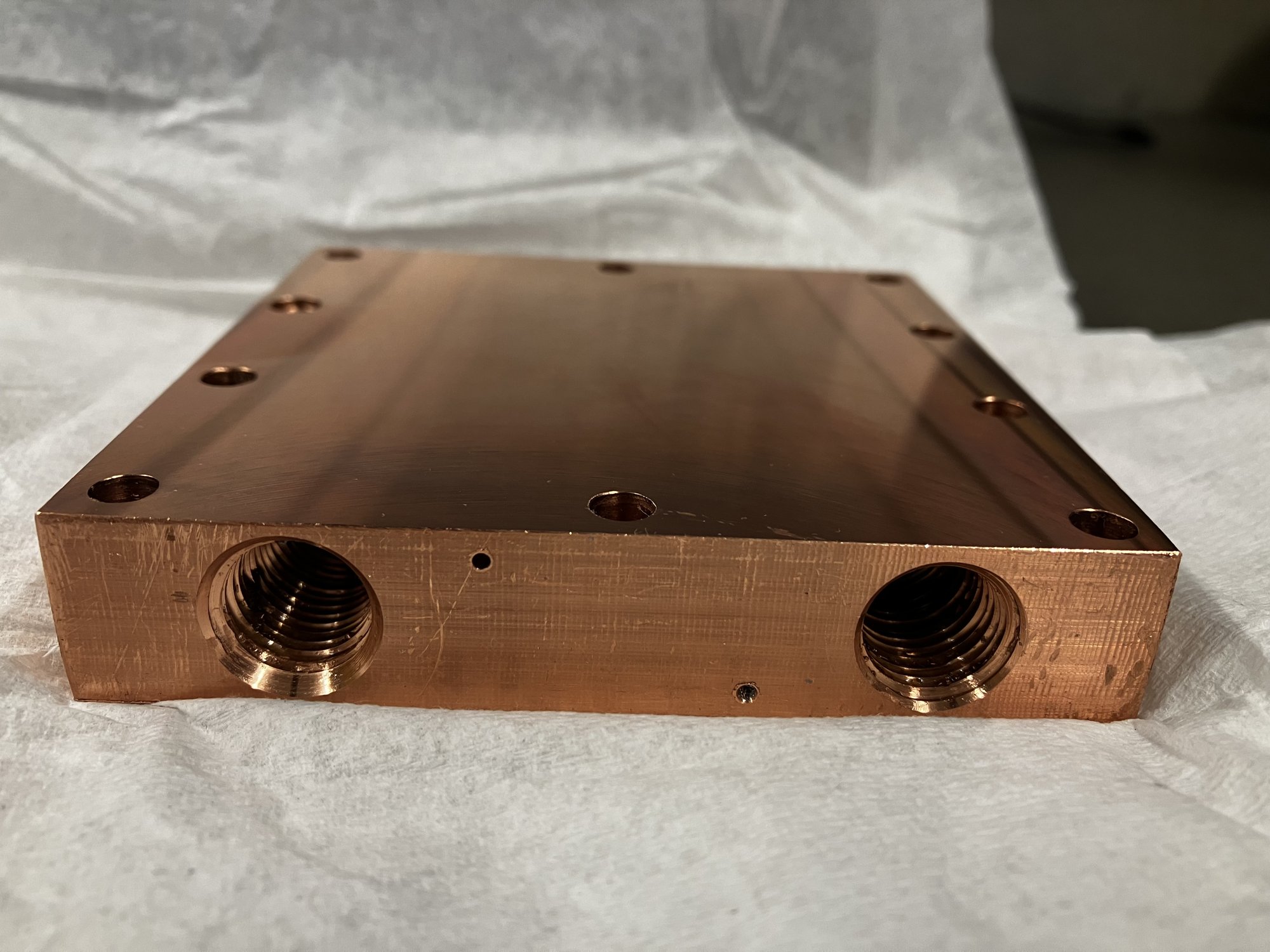
Figure 1. The condenser block as machined: two of the four 1/4 NPT water ports, ten clamp holes on the 85 mm pattern, and the thermocouple bores entering from the side faces.
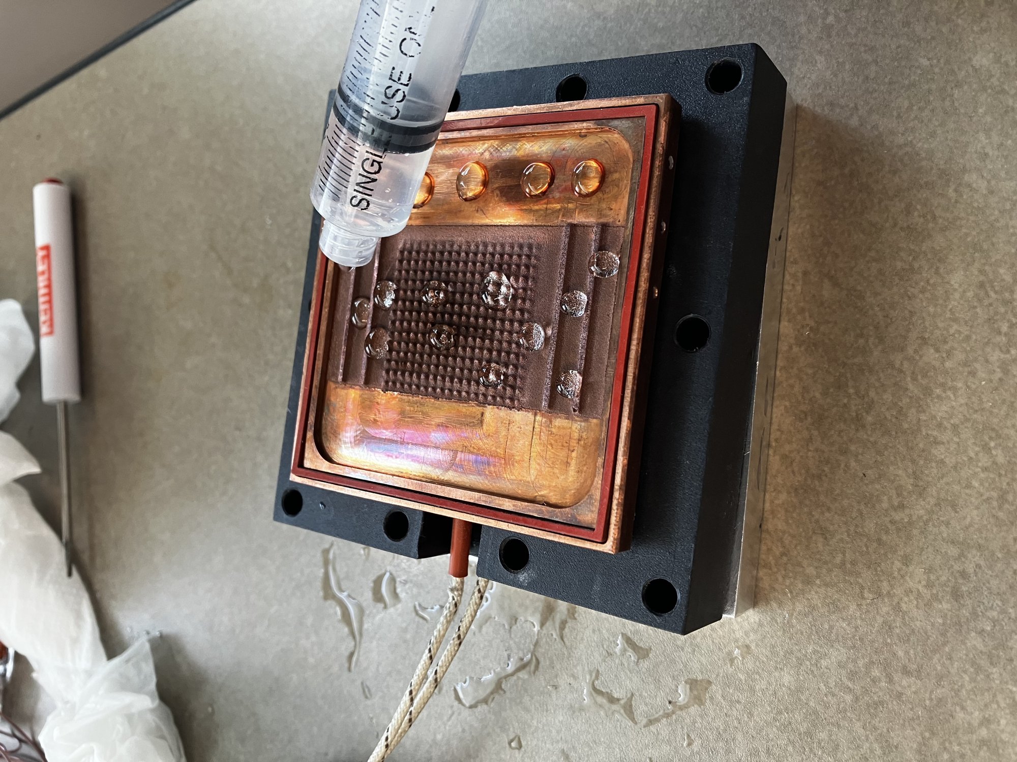
Figure 2. The vapor chamber substrate with the sprayed sawtooth structure, the laser-cut silicone gasket and the thermocouple leads, being filled by syringe.
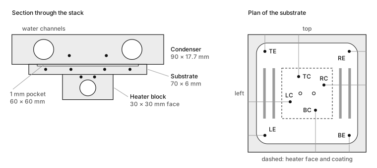
Figure 5. Where the beads sit. The section is cut across the water channels. The condenser beads are shown at a nominal height. In the plan, the grey bars are the sprayed channel walls and the open circles are the heater block beads, below the plate.
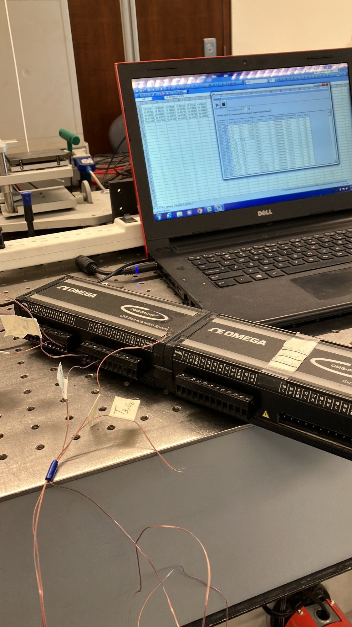
Figure 3. The DAQ with expansion modules and the labelled thermocouple leads.
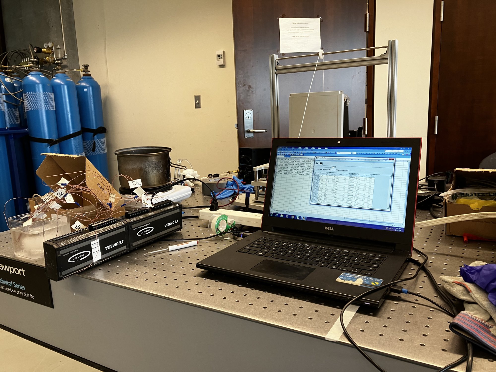
Figure 4. Two-point calibration of the thermocouples against an ice bath.
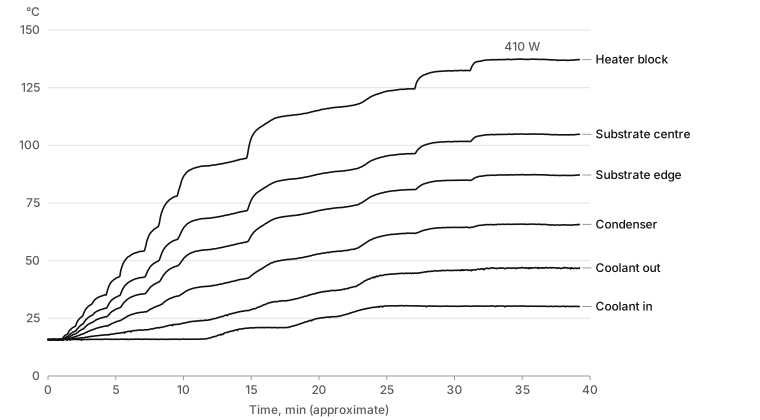
Figure 6. The charged test. Each line is the mean of the thermocouples at that location. The power was stepped up by hand and only the final step, 410 W, was recorded. The time axis assumes 0.66 Hz.
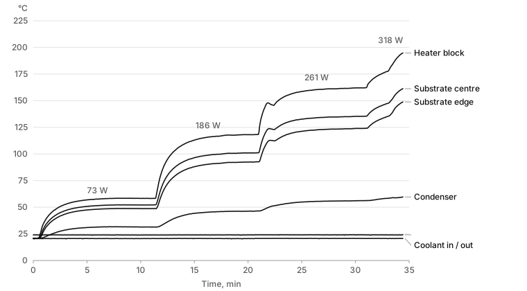
Figure 7. The dry control. The first three steps settled. The 318 W step was stopped with the heater block at 199 °C and still rising.
Video 1. The charged run. The field is the fitted model. The dots are the measurements, so a dot that stands out from the field is where the model is wrong.
Video 2. The dry control, on a wider colour scale.